Mesh liveries
A livery does not have to be paint alone. A mesh livery also carries a small 3D model of its own, which the simulator merges into, or attaches to, the aircraft’s model (see Merging or attaching): stripes, lettering or a registration as real geometry that stays crisp at any distance, or an extra part such as an aerial or a pod. Your model can even ride the aircraft’s moving parts, so a stripe across a door opens with the door.
You build the model in a 3D modelling tool that exports glTF for MSFS. Blender is a great free choice, and it is the one this page uses in its examples. The toolkit checks the model, compiles it with your livery, and writes everything the simulator needs to merge it.
- Which aircraft
- Before you start: get the aircraft’s moving-part nodes
- Modelling tips
- Adding a model to a livery
- Changing a material’s colour at build time
- Monolithic aircraft: merging or attaching
- Monolithic aircraft: model options and merged parts
- Modular aircraft: one model, split by part
- Compiling
Which aircraft
Mesh liveries work on MSFS 2024 aircraft, both monolithic and modular, including stock and Marketplace aircraft read through the Virtual File System. MSFS 2020 aircraft can carry mesh liveries too, but the toolkit does not build them for 2020 yet. Aircraft the simulator protects are not supported. See Supported aircraft.
Before you start: get the aircraft’s moving-part nodes
For a piece of your model to follow a moving part, it has to be parented to the aircraft’s own node for that part, with the same name and in the same place. The Paintkit Builder gives you those nodes as two files, and each has its own job:
- Build a 3D paintkit with Include parent nodes for merged models and Also write parent nodes as a separate file both selected.
- Use the paintkit model as your reference. Import it into Blender to see how the aircraft is put together: which parts hang under which node, so you know which node a door or a rudder moves with.
- Build your livery in the parent nodes file. It holds just the aircraft’s nodes, for every part of the aircraft, already in the right place, and none of its geometry. Model your meshes in it and parent each one under the node it should follow. A mesh parented to nothing stays still.
- Export that file as your livery’s model.
Working in the parent nodes file keeps the aircraft’s own geometry out of your livery’s model, and gives you every node whatever textures you chose for the paintkit.
What the tree should look like
Here is how a simple aircraft might look in Blender’s Outliner. The names are made up; every aircraft names its own nodes. A node (an empty in Blender) is a point the aircraft’s animations move, and the aircraft’s meshes hang under them:
Base aircraft (the paintkit model, for reference)
└── Airframe                  node
    ├── Fuselage              mesh     (the aircraft's own)
    ├── Rudder                node     moved by the rudder animation
    │   └── Rudder_Skin       mesh     (the aircraft's own)
    └── Door_L                node     moved by the door animation
        └── Door_L_Skin       mesh     (the aircraft's own)
Your livery’s model keeps the same nodes, with the same names in the same places, and hangs your meshes under them instead of the aircraft’s:
Your livery model (built in the parent nodes file)
└── Airframe                  node       from the parent nodes file, untouched
    ├── Fuselage_Stripes      YOUR mesh  stays with the airframe
    ├── Rudder                node       from the parent nodes file, untouched
    │   └── Tail_Logo         YOUR mesh  moves with the rudder
    └── Door_L                node       from the parent nodes file, untouched
        └── Door_Stripes      YOUR mesh  opens with the door
When the livery is built, each of your meshes ends up under the aircraft’s real node of the same name, so it moves exactly as that node does. The aircraft’s own meshes (Fuselage, Rudder_Skin, Door_L_Skin) are not in your file; the simulator already has them.
To parent a mesh in Blender, select the mesh, then Shift-click the node so it is selected last, and press Ctrl+P > Object (Keep Transform). Keep Transform leaves the mesh exactly where you modelled it.
Common mistakes, and what they do:
- A mesh left at the top of the tree, under no node: it stays still, even if it sits on a door or a control surface.
- A renamed node (
Rudderchanged toRudder_mine): it no longer matches the aircraft’s node, so the mesh does not move with the rudder. Blender’s.001on a duplicated node is fine; the toolkit ignores it. - A moved node: the mesh follows the aircraft’s real node, which is somewhere else, so it ends up in the wrong place. The Parent node checks warn about this.
- A mesh named the same as one of the aircraft’s nodes: it can be mistaken for that node. Give your meshes names of their own.
Modelling tips
- Export with an MSFS glTF exporter, such as the one for Blender. It gives every node the identifier the simulator merges by. A file without those identifiers, such as one from a general-purpose glTF exporter, is reported in the File checks, because its meshes may not follow moving parts.
- Use a decal material for anything laid over the paint, such as stripes and lettering. It blends over the aircraft’s surface instead of fighting it. An ordinary material is right for a solid part, such as an aerial.
- Lift geometry slightly off the skin, or give it a decal material, or it can flicker in the simulator where it meets the aircraft’s surface.
- One model per livery. If the model folder holds two, the build stops rather than guessing which you meant.
Adding a model to a livery
Select the livery’s Model node in the Workspace tree, then select Add a model to this livery, merged with the aircraft’s model. Turning it off later keeps your files.
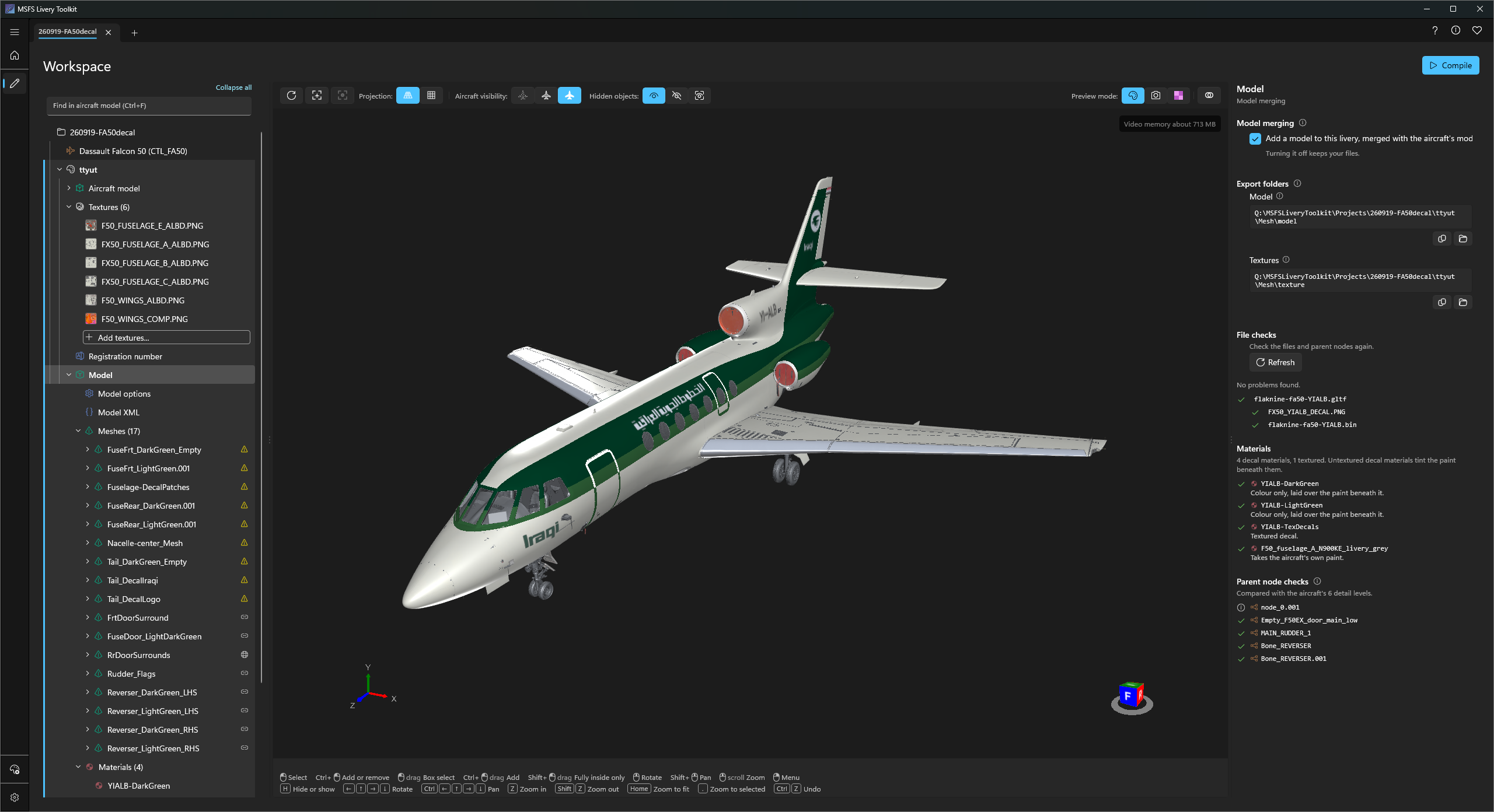
Export folders shows two folders, each with an Open button:
- Model: export the
.gltfand its.binhere. - Textures: where your model’s textures must already be before you export. See below.
This step is very easy to get wrong. Blender does not copy your textures into the Textures folder when you export. The exporter only writes down where each image already is. So the images must be in that folder, and Blender must be pointing at them there, before you export:
- Copy every texture your model uses into the Textures folder.
- In Blender, point each image at its copy in that folder (in the Image Editor, Image > Replace, or the image’s file path in its properties).
- Then export the model into the Model folder.
If Blender still points at the images somewhere else, such as your artwork folder, the File checks flag every image that is not in the Textures folder. Fix it in Blender and export again before you compile.
Keep your model and its textures on the same drive. The exporter writes each image as a path relative to the model, and a relative path cannot cross drive letters, so an image on another drive is silently left out and the material draws white in the simulator. Keeping them in the Textures folder above avoids this.
After each export, select Refresh to check the files again.
- File checks lists the model, its buffer and every texture it uses, and says if anything is missing or was not written by the MSFS exporter.
- Parent node checks lists the nodes your geometry hangs under and whether each matches the aircraft’s own node by name and position. Select one to outline the meshes hanging from it. These are warnings only and never stop a build.
- Meshes, a folder under the Model node, lists each mesh in your model with the node it is parented to. Select one to outline it in the viewport.
Seeing it on the aircraft
The viewport draws your model on the aircraft as you work. After re-exporting from Blender, select Refresh on the viewport’s toolbar.
Model alignment, in Display options, chooses how your model is placed:
- Global draws it exactly as you exported it, so a mesh parented to the wrong node looks wrong here too.
- Aircraft nodes moves each of your parent nodes onto the aircraft’s own node, which is where the simulator’s merge puts it.
Changing a material’s colour at build time
The Materials folder under the Model node lists each material in your model. Select one to change what it produces when the livery is built: its colour above all, so red stripes need no re-export of a green model, then its surface, and under Advanced, how a decal combines with the paint underneath.
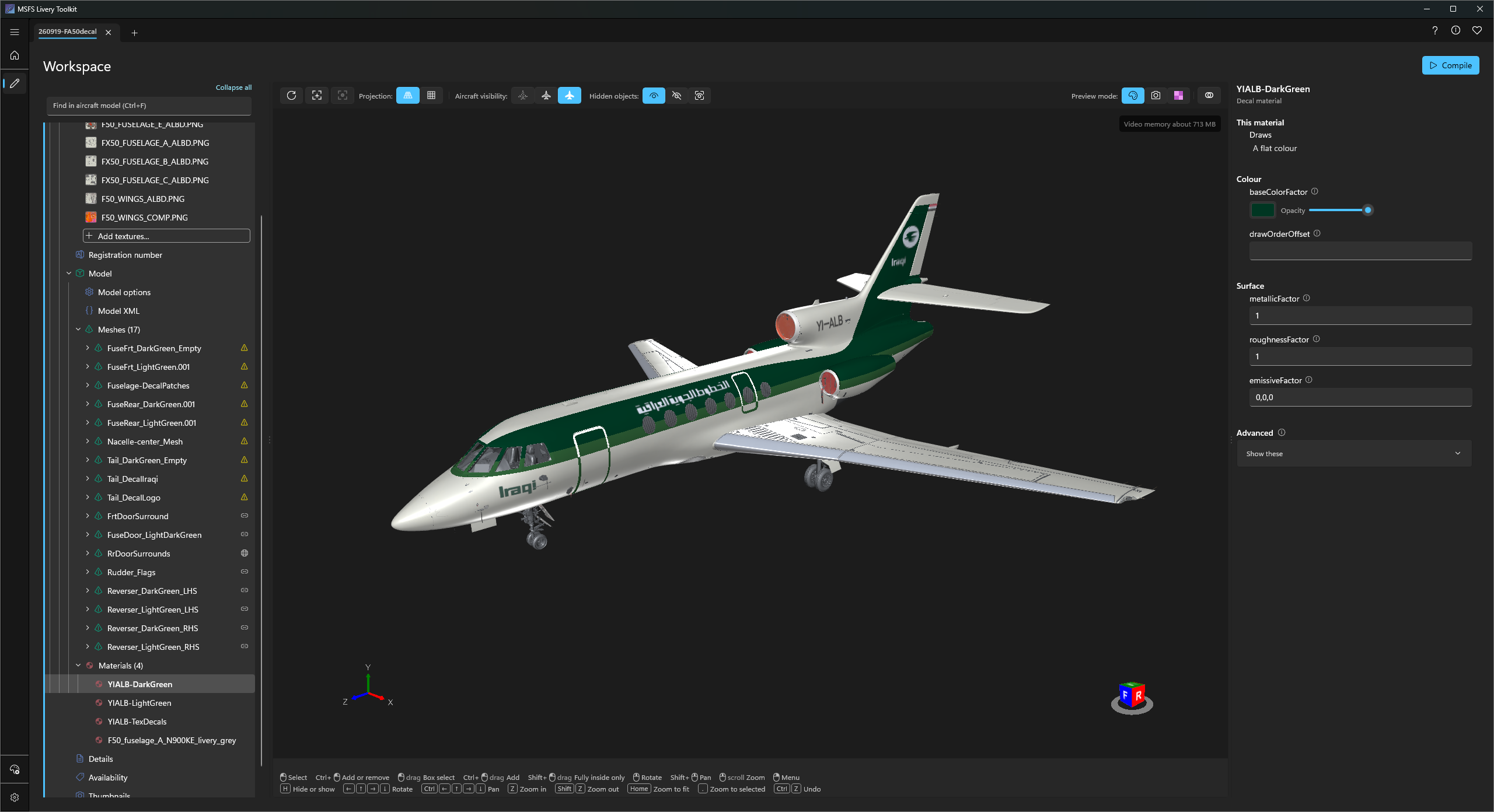
Your own file is never changed. The toolkit applies these settings to a copy while it builds, and Reset on any row puts back what you exported. On a textured decal the colour multiplies the texture, so it tints rather than replaces.
Monolithic aircraft: merging or attaching
On a monolithic aircraft, there are two ways the simulator can add your model to the aircraft:
- Merging joins your model into the aircraft’s own model, as if the aircraft’s developer had built it in. The SDK calls this Submodel Merging: it “merge[s] partially exported hierarchies based on unique identifiers that exist on the nodes in the model’s node hierarchy”.
- Attaching keeps your model separate and hangs it from a node of the aircraft’s model: the whole of it, or each piece from the node it should move with. The SDK calls this Model Attachments: “the attached model is not merged into the aircraft itself, and so has its own set of LODs”.
You don’t choose between them: the toolkit picks one for each livery, and the Model node’s title says which (“Model merging” or “Model attachment”). Both features are marked beta in the SDK.
Why merging comes first
Merging is the better method for a livery, so the toolkit uses it wherever the aircraft allows. The SDK says submodel merging “was initially developed with the intent of being able to more easily create mesh liveries for airplanes without having to re-export the entire airplane”. Attachments are meant for separate objects with their own detail levels, such as passengers, and the simulator restricts where they can go:
| Merging | Attaching | |
|---|---|---|
| What the aircraft needs | An Asobo unique ID (ASOBO_unique_id) on the nodes of its exterior model | Nothing: works on any aircraft |
| How a piece finds its moving part | By the node’s unique ID | By the node’s name |
| Following moving parts | At every detail level | Only on detail levels that have the node in the same place; elsewhere the piece stays still |
| Detail levels it appears on | Every one, unless you leave your model out of some (see below) | Not the most distant level, nor any level the aircraft only shows from far away; a single-level model is the exception (see the SDK rules below) |
| What the toolkit builds | One model shared by every detail level | Your model split into one file per moving part it follows, plus one for the pieces that stay still |
In short, a merged model behaves like part of the aircraft at every distance. An attached model is limited by the simulator’s rules for attachments, and by how the aircraft’s developer named and placed the parts at each detail level.
The SDK’s rules for attachments, and what the toolkit does with them:
- “The last LOD of a model may not have any attachments.” Your model is left off the aircraft’s most distant detail level.
- “LODs that have a ‘minSize’ of less than 5% may not have any attachments (this is to encourage merging meshes at that stage, for performance reasons).” The toolkit uses 2% instead of 5%, because at 5% pieces visibly disappeared too early on aircraft tested in the simulator.
- “Attachments need to be attached to every LOD individually.” The toolkit writes the attachments for every detail level it can, so you don’t have to.
When the toolkit falls back to attaching
The unique IDs are a feature of the base aircraft, not of your model: the MSFS exporters write them when the aircraft’s developer exports the model with that option on (the SDK’s merging page tells developers to “make sure the ASOBO_uniqueID is enabled”), and some aircraft are exported without them. Merging into a model without them doesn’t just fail quietly: the simulator can stop drawing the aircraft’s whole exterior model.
So before it builds, the toolkit reads the aircraft’s exterior model:
- Every detail level has nodes with unique IDs: your model is merged.
- Any detail level has none, or the model can’t be read: your model is attached.
When attaching, each piece follows the nearest node above it in your file whose name matches a node in the aircraft. Blender’s .001 suffix on a duplicated node is ignored, but a name the aircraft uses more than once is never matched, since the piece could go to either. On a detail level where the aircraft doesn’t have that node, or has it somewhere else, the piece is attached fixed for that level instead of guessing.
What you will notice on an attaching aircraft: a piece on a part the aircraft stops drawing at a distance stays still from that distance on, and your model is left off the most distant detail levels. The Model XML node greys out those levels and quotes the simulator’s rule.
Modular aircraft don’t need this choice: the simulator adds a livery’s model to each part of the aircraft itself, as described below.
Monolithic aircraft: model options and merged parts
On a monolithic aircraft the Model node has two more nodes, each with a preview of the file the toolkit will write:
- Model options holds the four
[model.options]settings, copied from the aircraft into your livery’smodel.CFG. Change one only if your livery needs to differ. - Model XML lists the extra models the aircraft merges over its own, under each detail level. All are kept unless you clear one, which is what you want when your model replaces it, such as a backing plate behind a registration. Your own model can be left out of individual detail levels, which is how you drop it from the most distant ones.
Modular aircraft: one model, split by part
A modular aircraft is built from parts, and the simulator adds a livery’s model to each part separately. So the build splits your one model for you: each mesh goes to the part that owns the node it is parented to, and a mesh parented to nothing goes to the main part and stays still.
The Parts table on the Model node shows where each mesh will go. Some parts of an aircraft cannot take a livery’s model at all; the table says so, and meshes parented there are left out of the build.
Compiling
Compile as usual. The toolkit compiles your model and its textures with the livery, writes the merge files, and points the livery at them. On a monolithic aircraft that sets the livery’s model field, which is why it is locked on the Details node while a model is enabled.
Check the result in the simulator: open and close the doors and move the controls to confirm every mesh follows its part.